In connection with absolute position feedbacks (resolvers, singleturn and multiturn SinCos absolute encoders) can optionally functions for position reconstruction used .
These functions enable it to restore
the correct actual position with the restart of the device/machine, and namely taking into account taking the resulting position offset by any movements done in off state. Using this function, specific position data must be stored in the inverter / controller during the power down (retain data).
There are two reconstruction functions to distinguish between:
-
Encoder position reconstruction in device (firmware of the servo inverter i750 + i950);
The function is per default enabled and can be deactivated via 0x2DE0:28 Bit0
Machine position reconstruction in the MotionAxis
This function can be activated via subindex :081Any distances traveled outside the encoder's measurement range will be lost. Any distances traveled outside the encoder's measurement range will be lost. Any distances traveled outside the encoder's measurement range will be lost. Any distances traveled outside the encoder's measurement range will be lost. Any distances traveled outside the encoder's measurement range will be lost.
Common advantages of these features:
-
Expansion of the usable positioning range of the application, via the absolute display range of the used absolute encoder used, which is usually set to a to 4096 encoder revolutions.
- The absolute encoder can be mounted on the machine with any encoder value and in any mechanical position.
During commissioning, the display range of the encoder does not have to be laboriously adjusted to the mechanical travel range in order to avoid overflow.
Advantage and Application of encoder position reconstruction in device (firmware):
-
In topologies with a third-party motion controller, the reconstructed position is provided to the superimposed motion software.
-
i950 extended safety: The 'mini homing' function can also be used with single-turn absolute encoders or resolvers.
Explanation of the function of encoder position reconstruction using two examples
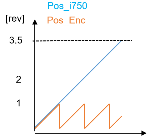
Example 1 (single-turn absolute encoder):
Sequence:
-
Single-turn absolute encoder with active encoder evaluation (control card powered) rotated by
3.3 revolutions, i.e. three times beyond its display range. -
Then switch off the device and, while it is switched off, move it a further 0.2 revolutions.
-
Switch the device back on. The actual position is reconstructed.
Result
-
The encoder position reconstruction causes the actual position to be initialized correctly with 3.5 revolutions.
The value corresponds to the last actual position when the device was switched off plus the additional offset that occurred in the switched-off state.
-
Without encoder position reconstruction, the actual position would only have been initialized with 0.5 revolutions, i.e., the (modulo) value within the absolute display range of the encoder (red curve). Any distances traveled outside the encoder's measurement range will be lost.
Example 2 (multiturn absolute encoder):
Procedure:
-
Switch on the servo inverter immediately after mounting the motor with a multiturn absolute encoder, e.g. an AM128:
Actual position = 1.0 revolution. Then m
In order for the encoder position reconstruction to be possible, the last valid position value must be stored (persisted) in the device in a manner that is secure against power failures when the servo inverter is switched off.
This means that the reconstruction can only be accurate if it is performed on the same servo inverter on which it was persisted.
ove the encoder two revolutions in the negative direction (CCW) to the reference position.
The encoder is thus turned in the CCW direction beyond its absolute display range.
-
Switch on the power to the servo inverter and reinitialize the actual position.
Result:
-
With and without encoder position reconstruction, the initialized actual position (current position 0x6064) is different:
|
Encoder position reconstruction
(0x2DE0:028 Bit0) |
|
Active
Bit0 = FALSE (Default) |
Inactive
Bit0 = TRUE |
Current position (0x6064) BEFORE switching on the power |
minus 1 rev |
minus 1 rev |
Current position (0x6064) AFTER power-up |
minus 1 rev |
plus 4095 rev
|
This the encoder position reconstruction possible , the when switching off the servo converter the last valid position value in device battery-backed stored (persistent) . The means that that the reconstruction only fit if if it on the same servo converter , on the also persisted.
In order for encoder position reconstruction to be possible, the last valid position value must be stored (persisted) in the device in a power failure-proof manner when the servo inverter is switched off.
This means that reconstruction can only be accurate if it is performed on the same servo inverter on which it was persisted.
Usage of the 'encoder position reconstruction in the base firmware' feature
A major advantage of encoder position reconstruction is that no initial position needs to be taken into account when mounting the encoder, which would be necessary if this were the only way to prevent an overflow in the encoder's display range during operation and also in the event of unexpected coasting.
When using the i750 + i950 servo inverters with Lenze MotionControl, whether in the axis itself or in a Lenze controller, referencing and machine position reconstruction take place in the application (Motion).
The selection of the encoder position reconstruction (0x2DE0:28 Bit0) can be arbitrary in all these cases; there is therefore no reason to change the default (0x2DE0:28 Bit0 = FALSE).
When using the i750 / i950 base and i950 TA CiA402 Advanced with a third-party motion controller AND position encoders with absolute information, the application software developer decides whether encoder position reconstruction should remain activated in the base firmware, depending on the application requirements.
Under what application conditions must encoder position reconstruction be disabled (0x2DE0: Bit 0 = TRUE)?
Here, the encoder position reconstruction can also remain activated if
- If re-homing is not possible or desired after replacing the i950/i750.
- AND the actual position 0x6064:0 no longer corresponds to the actual encoder position without the offset being applied.
The actual position (0x6064) no longer corresponds to the actual encoder position if
either the “Set Actual Position Start Value” function (0x2983 + 0x2984) is used.
In this case, the position from 0x2983 is transferred to 0x6064:0 using 0x2830:0 Bit5 = FALSE/TRUE.
With the i950 TA CiA402 Advanced, the position is also transferred using 0x6040:0 Bit15 = FALSE/TRUE.
or axis-based homing is used with one of the modes from homing method 0x6098 (only with i950 TA CiA402 Advanced).
Important:
If you choose not to perform encoder position reconstruction (Bit 0 = TRUE), you must ensure that the encoder’s operating range is not exceeded. In some cases, this may mean that an encoder must be aligned to a reference position within the machine’s kinematics prior to installation.
In all other cases, encoder position reconstruction can remain enabled.
This causes retain data to be stored in the i750/i950 base unit.
In this case, it must be ensured that the servo drive is re-homed if it is replaced at a later time. This can be monitored, for example, in the higher-level controller by reading and comparing the servo drive’s serial number. If this unique serial number has changed from the value stored during initial homing before, then homing must be performed again after replacement.
Summary and relevant indexes
Index |
Name |
Info |
0x2DE0:28 |
Service settings: Compatibility |
Bit0 = TRUE deactivates the encoder position reconstruction This is used if the servo drive cannot/should not be re-referenced when it is replaced. However, it also requires the initial alignment of the encoder so that the position in its display area does not overflow!
|
0x2983:0 |
Actual position Start value |
Position value with which the actual position 0x6064:0 is to be set or offset; depending on the mode in 0x2984:0
|
0x2984:0 |
Set actual position mode
|
0: Absolute : This value is transferred to 0x6064:0 when the actual position is set 1: Relative : The value in 0x2983:0 has an additive effect on 0x6064:0 when the actual position is set
|
0x2830:0 |
Inverter control word |
Bit 5 = FALSE/TRUE : The value from 0x2983:0 is transferred to the actual position 0x6064:0 or offset against it.
|
0x6040:0 |
CiA control word |
Bit 5 = FALSE/TRUE : The value from 0x2983:0 is transferred to the actual position 0x6064:0 or offset against it.
|
Good to know:
Check whether 0x6064:0 corresponds to the actual encoder position without calculated offset.
- For the resolver
The value displayed online in actual position rotor angle 0x2DDE:0 multiplied by 32 must correspond to the value from actual position 0x6064:0 (with a few increments tolerance + at default 0x608F:1 = 16 bits). - For the Hiperface absolute encoder
The value displayed online in Motor encoder settings (HIPERFACE): Actual position (raw data) 0x2C41:6 multiplied by k must correspond to the value from Actual position 0x6064:0 (with a few increments tolerance + at default 0x608F:1 = 16 bits).
Encoder Typ |
Auflösung 0x2C41:6 |
k |
AM1024 | 15 Bit | 2 |
AM512 | 14 Bit | 4 |
AM128 | 12 Bit | 16
|
Deleting inappropriate reconstruction information
To ensure that no inappropriate reconstruction information is stored in the base unit of servo converters that are not brand new, this information can be deleted by executing the axis command “Reset position to native value” (0x2822: 40 or 41). This transfers the raw position of the connected absolute encoder to 0x6064 and sets stored offsets to zero.
