Question:
How can a dead time compensation be realised with the Servo Inverter i950 BS/ES with the TA Sync And Correction (0x4000:0 = [41])?
Answer:
The actual values transmitted by the encoder are subject to dead time in the encoder axis after signal transmission.
To compensate for this dead time, it is possible to extrapolate the actual values provided by the encoder axis.
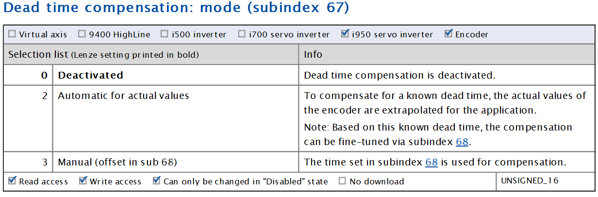
The dead time compensation can be activated in subindex 67.
In the case of a master-slave coupling in an i950 servo inverter used as an (EtherCAT) master, there is also the option of delaying the setpoint generated for the master: with subindex 67 = 1, a position- or speed-accurate synchronisation to the connected slave axes is achieved.
Parameter
Effectiveness of the dead time compensation with master-slave couplings (master setpoints as master value source)
The following illustration shows a master-slave coupling with a master axis as the master value source.
The setpoints of the master are only effective in the slave after the EtherCAT signal propagation time (Δtcomm). The setpoints of the slave thus lag behind those of the master by Δtcomm.
In order for the same setpoints to be effective in both drives at the same time, the signal propagation time Δtcomm must be compensated (0x500A:067, 0x500A:068).
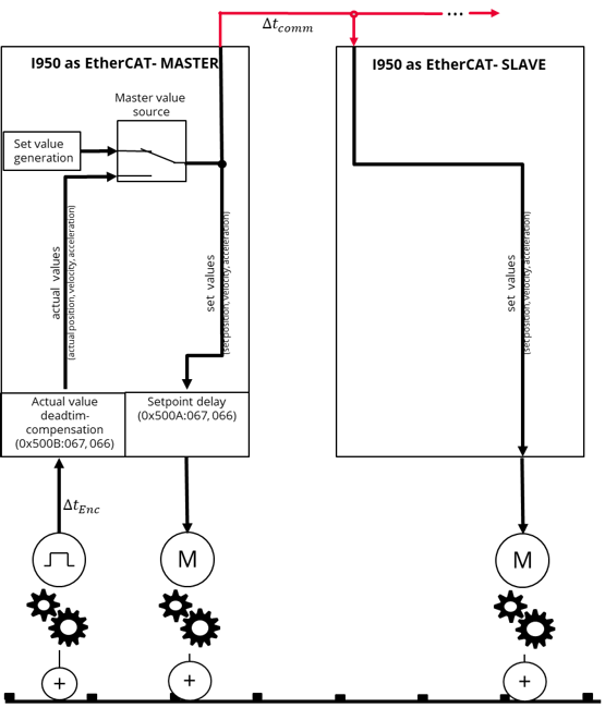 Master-slave coupling (master axis as conductance source)
|
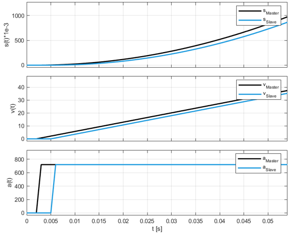
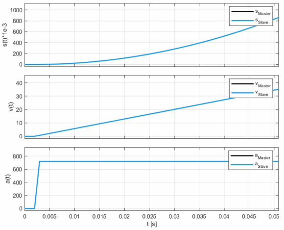
The following signal curves show the master-slave setpoints without and with active dead time compensation (mode 1: automatic for setpoints ) during an acceleration phase.
a)
|
b) |
Signal characteristics without (a)) and with (b)) active dead time compensation
|
In mode 1 (automatic for setpoints), the setpoints are transferred to the master axis delayed by a preset time of 3ms.
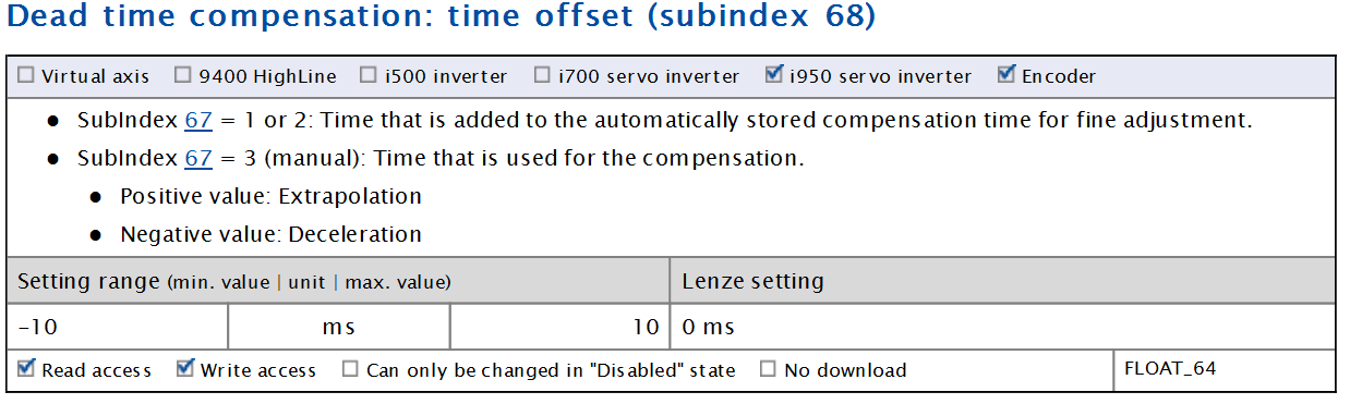
If necessary, the compensation can still be fine-tuned via sub-index 68.
Positive values: Further delay of the master's setpoints (3ms+0x500A:068).
Negative values: Less delay of the setpoints of the master (3ms-0x500A:068)
In mode 3 (manual), the time to be compensated can be specified manually in 0x500A:068.
Effectiveness of dead time compensation with master-slave couplings (encoder as conductance source)
The following figure shows a master-slave coupling with an encoder as the master value source.
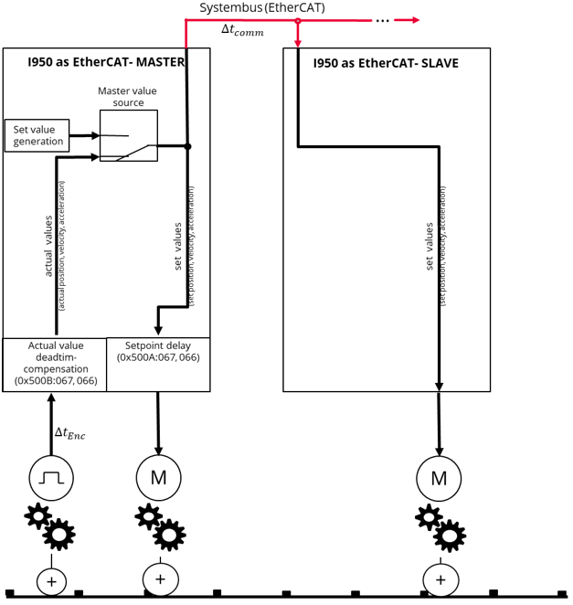
|
The actual values of the encoder are only effective after a signal runtime ΔtEnc+2ms PLC clock in the axis of the EtherCAT_Master.
If this master value is transmitted to further slaves, this value is only effective in the slave axes after ΔtEnc+2ms PLC clock+Δtcomm.
In order for the same setpoints to be effective in both drives at the same time, the encoder actual values must be extrapolated by the maximum signal propagation time (0x500B:067 = 3, 0x500B:068 = ΔtEnc+2ms PLC clock+Δtcomm).
Furthermore, the setpoints of the master axis must be delayed by the signal propagation time Δtcomm, analogous to the procedure in the previous section. (0x500A:067 =2).
Automatic Translation