Corrected from:
PLC Designer V3.5
Library L_SM3_DriveUtil.lib V3.5
Response of the new version?
The L_SMC_Multiturn block serves to save the number of revolution overflows with mains failure protection.
Which products are affected?
PLC Designer from V3.3 in combination with Lenze Controllers 3200 C/p500 and i700 servo inverters
Library L_SM3_DriveUtil.lib ab V3.3
What happens?
When the controller is switched on again, the actual position of the i700 servo inverter does not correspond to the position when switching off the controller.
Example:
Linear axis, 1 motor revolution corresponds to 1 mm axis feed
Position before switching off: 123.456 mm
Position after switching on the controller again: 0.456 mm
When does the problem occur?
The L_SMC_Multiturn function block shall simulate the multi-turn encoder functionality for a single-turn absolute value encoder. I.e. the FB can save the number of revolution overflows with mains failure protection.
Due to the function restriction, it may happen that the L_SMC_Multiturn function block sets the number of revolution overflows to 0 after mains switching. Therefore, when switching on the controller again, the actual position of the i700 does not correspond to the position when switching off the controller.
Diagnostic options?
Check if the L_SMC_Multiturn function block is used in your PLC project.
Short-term measures/recommendations?
Add the following IF instruction to your PLC project:
IF (SM_Drive_ETC_i700.DSP402_Statemachine.wStatusWord <> 0) THEN
myL_SMC_Multiturn(xExecute:= TRUE, Axis:= SM_Drive_ETC_i700);
END_IF
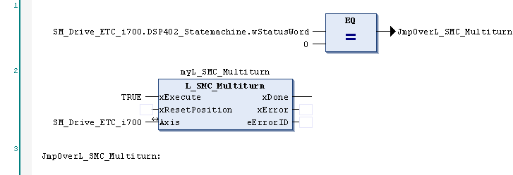
Or, alternatively, when using the function block diagram (FBD) programming language, add the following jump instruction to your PLC project:
Adapt the axis name SM_Drive_ETC_i700 in the extended logic to the axis name of your project (see variable name connected at the axis input of the L_SMC_Multiturn function block).
Evaluation
When the L_SMC_Multiturn function block is used to simulate a multi-turn encoder functionality for an encoder connected to the server inverter i700, there may occur an offset between the mechanical position and the actual position in the PLC project. Travel commands will be carried out as programmed in a shifted measuring system. This can lead to machine damage.