Which products are affected?
9300 vector 0.37…90 kW SW V7.1
Applications
Connecting the drive controller to a coasting machine, e. g. a fan.
Function description
In order to ensure that the flying restart circuit is not started before the motor has been demagnetised a controller or pulse inhibit is internally prolonged to a minimum time.
Due to this measure it can be avoided that at the beginning of the flying restart circuit the search current is injected into the machine which is still excited and thus leading to an irritation of the flying restart circuit or to the determination of a faulty speed.
Since the demagnetisation time depends on the motor the Lenze setting is determined online from the double rotor time constant TR and entered under code C0132.
C0132[ms] = TR[ms] * 2 = 2 * Stator inductance C0092 in [mH] / Rotor inductance C0082 in [Ohm]
Code C0132 can also be adapted manually from 0 ms to 9999 ms. If a peak current is detected at the beginning of the search current injection the machine has not yet been de-excited sufficiently and it may be useful to further increase code C0132.
When motor selection (C0086), stator inductance (C0092) or rotor resistance (C0082) are changed code C0132 is reset to the motor-dependent Lenze setting.
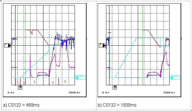
The following figure shows a peak current at the beginning of the search current injection when C0132 = 469 ms. However, oscillogram a) shows that this does not affect the speed determination in a negative way. Therefore, it is not compulsory to increase C0132. Oscillogram b) shows the sequence when C0132 = 1500 ms. In this case there is no peak current at the beginning of the search current injection.
Description of the phases of a flying restart circuit (see designation of the phases in oscillogram a):
1. Controller is inhibited via terminal 28.
2. Controller is enabled via terminal 28 but the minimum time of the controller inhibit specified under C0132 (here 496 ms) has not yet expired.
3. Start of flying restart circuit and injection of search current. Since the machine has not yet been de-excited sufficiently a peak current occurs at first and the search current injection is restarted. The search frequency is indicated under MCTRL-FACT.
4. By determination of a current minimum the controller recognises that the search frequency corresponds to the current machine speed. The output voltage MCTRL-VACT is increased along a ramp in the following synchronisation phase.
5. When the synchronisation phase has been completed and the decay time under C0133 has expired the ramp function generator is re-enabled and the motor is accelerated to the setpoint speed. The flying restart circuit has been completed successfully.
Fig.: Signal characteristic when executing a flying restart circuit as a function of C0132
CH1 (pink): Motor current MCTRL-IACT (10 % / div)
CH2 (red): Rotating field frequency MCTRL-FACT (2 % / div)
CH3 (blue): Output voltage MCTRL-VACT (20 % / div)
CH4 (turquoise): Setpoint speed MCTRL-NSET2 (20 % / div)