 Question:
 How can you check a 24 VDC PM brake for wear without dismantling it?
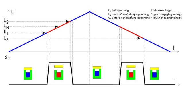
Answer: The electrical data measured when the brake is applied can be used to check the wear degree of the friction linings. The electrical data can be determined as follows with either voltage or current being considered for the evaluation.
The wear check may be used for the following brake types:
- 86_61XXHXX
- 86_62XXHXX
- 86_61XXEXX
- 86_62XXEXX
(For type designation, see brake nameplate or SAP BOM for the MCS or MCA motor, e. g. via the Lenze service team)
If I3, i. e. the current during brake application is used (better method), the measured values are not influenced by the self-heating of the winding. However, you still have to observe that the magnet will still have TA during the measurement.
If U3 is used as evaluation criterion (easy, rough method), it must be ensured that the brake and its winding have a temperature of TA~20°C. Otherwise, the measured value would be falsified. This also means that the test must be carried out very quickly to ensure that the winding will not heat up.
Requirements / required material:
- Adjustable 0-24 V DC voltage source
- Multimeter
How to carry out the current method:
- Measure brake and ambient temperature: TA
- Measure the winding resistance of the brake: RTA
- Connect the adjustable voltage source (observe polarity) within earshot to the brake.
- Connect the multimeter for DC-current measurement to the voltage source.
- Set the voltage source to 24 V.
- Switch on the voltage source.
- Brake release becomes audible.
- Reduce the voltage in max. 10 s until brake application becomes audible.
- The current value at the time of brake application is: I3
- When repeating the test, observe that the brake heats up during the test. An adequate cooling period must be observed.
- Calculate: R20 = (RTU * (20 + 235))/(TU + 235)
Does the brake have to be replaced?
-
At 20 °C, U(3,limit) = 5 V may be considered as limit value at which brake wear may be expected.
-
If I3 = U(3,limit)/R20, a mechanical brake test is required and the brake must be replaced, if necessary.
How to carry out the voltage method:
- Ensure a brake and ambient temperature of approx. TA = 20 °C
- Connect the adjustable voltage source (observe polarity) within earshot to the brake.
- Connect the multimeter for DC-current measurement to the voltage source.
- Set the voltage source to 24 V.
- Switch on the voltage source.
- Brake release becomes audible.
- Reduce the voltage in max. 10 s until brake application becomes audible.
- The voltage value at the time of brake application is: U3
- When repeating the test, observe that the brake heats up during the test. An adequate cooling period must be observed.
Does the brake have to be replaced?
-
At 20 °C, U(3,limit) = 5 V may be considered as limit value at which brake wear may be expected.
-
If U3 = U(3,limit), a mechanical brake test is required and the brake must be replaced, if necessary.
Search terms: Wear check; brake wear; PM; brake service; brake maintenance
