Question:
What do you have to observe when dimensioning and fusing a 9400 multi-drive network using a 100 A-busbar system?
Answer:
To allow an energy exchange between the devices, a busbar system is used to interconnect 9400 Multi Drives on the DC end. Usually, a centralised 9400 power supply module is used for the mains supply of the drive network. The power supply module is directly connected to the busbar system. As an alternative, the drive network can also be supplied from any DC source. In this case, the connection cables of the DC source are connected with the busbar system via a DC-feeding point.
The busbars, the busbar outputs of the 9400 power supply modules and, if necessary, the DC-feeding points are each designed for an effective current of 100 A.
Overload protection:
The rated current of the 9400 DC-feeding points and the busbars is 100 A. During operation, this value must not be permanently exceeded to avoid overload and damage resulting from overload.
By an appropriate dimensioning of the drives in the DC-bus connection and, if necessary, of the power requirement profiles, the system engineer must ensure in all operating states that the total current via the feeding point and the busbars will not lead to overload.
In general, the mains fuses in the mains supply are used as an overload protection for the entire drive network.
Short-circuit and earth-fault protection:
The backplanes of the multi-drive devices and the busbar connections of the power supply modules each contain a DC fuse for the +UG connection. The DC fuses are only designed to minimise bigger damage to additional components, if necessary, if a short-circuit should occur in the DC-bus connection.
In specific applications, the user may only want the controller concerned to be disconnected from the DC bus connction through tripping of the DC fuse if a defect occurs, and the other controllers are expected to continue operation.
The DC fuses are not designed to protect the cables and components from overload, i.e. permanently excessive power with a correspondingly excessive current load.
The busbar system itself is supposed to be short-circuit and earth-fault-proof (see glossary: doc ID
202300041). In so far, you could even completely do without DC fuses in this 9400 multi-axis DC-bus connection if the cables are, as usual, protected by the mains fuses.
Notes for the connection of the DC feeding points:
The connection terminals at the top and bottom of the DC feeding points are
not designed for looping through the DC bus to additional DC busbar systems. The terminals are designed for a convenient connection from the top or from the botton, depending on the structure of the control cabinet installation.
In particular cases, looping through is possible if the rated current of 100 A is not exceeded.
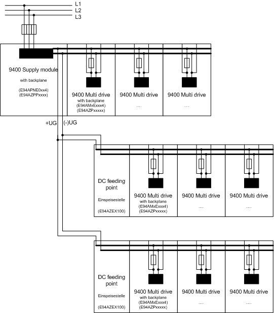
Several multi-axis networks with DC feeding point at a powerful 9400 power supply module:
If required, it is also possible to connect several separate 9400 multi-axis networks (each with a separate busbar) in parallel to a 9400 power supply module that has a corresponding capacity, see figure. The connection terminals of the DC feeding points are used for the cabling to connect the multi-axis networks in parallel. The connection terminals are each mounted on the left-hand side of the busbars.
The wiring between the 9400 power supply module and the DC feeding points of the multi-axis networks again needs to be short-circuit and earth-fault proof (see glossary: doc ID
202300041).