Question:
In which way behaves the absolute motor position (output signal MCTRL-PHI-ANG) after initialisation and during drive operation of the 9300 servo inverters?
Answer:
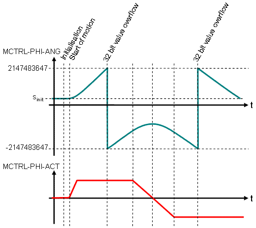
The outpupt signal MCTRL-PHI-ANG represents the absolute position of the motor shaft (if feedback system is mounted on the motor shaft) or the load (load-side mounted feedback system). This signal is internally stored as a 32 bit value and can take values in a range of - 2,147,483,648 to + 2,147,483,647 [Increments]. During normal drive operation MCTRL-PHI-ANG is an accumulation of the velocity signal MCTRL-PHI-ACT (functionality similar to an integration of MCTRL-PHI-ACT by a function block PHINTx).
Depending of the position feedback system MCTRL-PHI-ANG can already take values unequal to zero directly after initialisation of the servo drive:
- Resolver: Depending on the absolute rotor position MCTRL-PHI-ANG is initialized in a range of - 32,768 ... + 32,767 [Increments].
- Single turn absolute encoder: Depending on the absolute rotor position MCTRL-PHI-ANG is initialized in a range of 0... + 65,535 [Increments].
- Multi turn absolute encoder: Depending on the absolute rotor position MCTRL-PHI-ANG is initialized in a range of 0... + 268,435,455 [Increments].
- incremental encoders and sinus cosinus encoders: Due to missing information about the absolute rotor position MCTRL-PHI-ANG will initialize with a value of 0.
After initialisation the value of MCTRL-PHI-ANG will continuously count up/down depending of the motor rotation/Load movement. MCTRL-PHI-ANG will
not be limited depending on the value range of the position feedback system! The only limitiation will occur due to the limited value range of 32 bit variables (- 2,147,483,648 ... + 2,147,483,648 [Increments]).
An example diagram is shown below: After initialisation MCTRL-PHI-ANG has an initial value of Sinit. Starting from this value MCTRL-PHI-ANG will take any value between - 2,147,483,647 to + 2,147,483,647 [Increments] depending on the motion profile of the drive.
Note:
Using a resolver feedback system the absolute rotor position is also displayed by the analog signal MCTRL-PHI-ACT. Because the analog signal MCTRL-PHI-ACT is a 16 bit signal this signal is always limited to a range of - 32,768 .... + 32,767 and represents the resolver position also during drive operation.