Question:
In case of rotary table and similar applications often cyclic measuring systems are used (e. g. 0.0 ... 360.0 °). These represent a clock pulse on the load side. If this clocking time on the load side (e .g. 360.0 °) is converted to an incremental size, this results in an incremental value by means of the gearbox ratio (numerator/denominator) and the feed constant. Eventually, this incremental value has a decimal code. Decimal codes in incremental sizes are, however, not considered in the available integrator blocks (PHINT3, PHINT4) with cyclic overrun.
Is there a possibility to represent a measuring system for a rotary table in spite of incremental clock pulses
with decimal codes?
Answer:
For using the integrators PHINT3 or better PHINT4 for representing the rotary table measuring system an incremental integer clocking time is required to represent the measuring system permanently drift-free. Consequently, an
imaginary clocking time is to be created, which shows
no decimal code compared to the
real incremental clock pulse with decimal code. In order to convert the proper motion of the axis from the real to the imaginary measuring system, conversion blocks (e. g. CONV3) can be used, which are set correspondingly in their numerator/denominator relation.
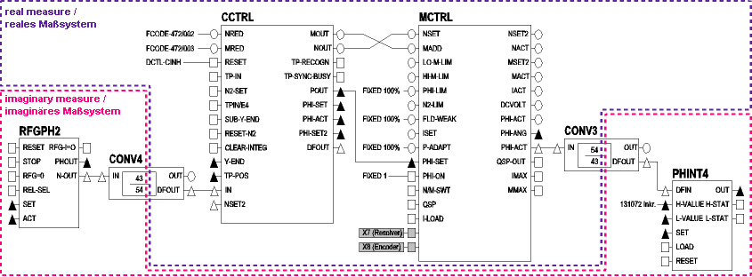
If in opposite direction motion profiles, which can easily be calculated in the imaginary measuring system (e. g. positioning via the RFGPH2 function block), are to be operated in the real measuring system (motion of the axis), another conversion block (e. g. CONV4) can be applied using as numerator / denominator evaluation the opposite relation as the conversion block from the real to the imaginary measuring system.
Example:
A rotary table is operated by a drive with a gearbox ratio of 43 : 54 and a feed constant of 360 °/rev. A clocking time of 360 ° results incrementally to
Clocking time [incr.] = 360 [°] * 65536 [incr.] / 360 [°/rev] * (43 / 54) = 52186,0740740740729962...
In the imaginary measuring system a machine clocking time of 360° is to be represented on an integer incremental clocking time of 65536 incr. by means of the PHINT4 function block. The MCTRL-PHI-ACT angle difference signal is used for representing the proper motion of the drive. When the proper motion is calculated in the imaginary measuring system the gearbox ratio is consequently to be considered in the numerator/denominator evaluation of the converter block (numerator=54, denominator=43). The upper limit of the PHINT4 function block is to be set correspondingly to 65536 increments, so that the function block overruns the imaginary clock-pulse limit.
When motion profiles are determined in the imaginary measuring system the procedure is the other way round: The angle difference signal is to be evaluated in relation 43 : 54. The angle speed adapted to the real measuring system can e. g. be transferred via the CCTRL-NSET2 input to the MCTRL function block, where it causes the desired motion.
Tip: The imaginary clocking time should always be similar to the real clocking time. This results in evaluation factors in the CONVx function blocks, whose values are almost 1. Otherwise residual value storages in the converter blocks could lead to undesired jumps in the setpoint signal.
Note: The presented function block interconnection illustrates the real and imaginary measuring system. It is, however, no independent executable parameter setting, but is to be added by the user corresponding to the demanded functionalities. Due to the available function blocks the measuring system for a rotary table can easily be realised with the 9300 EK electronic cam. The individually examined function is not directly dependent on the cam technology and uses no cam function blocks.