Which products are affected?
ESP-SPAC-CAM1 – Software Package Cam V1.5 (
LenzeCamControl1V0105.lib libraries)
What happens?
Compared to the assigned master value position (position output) the absolute master angle may be shifted if the phase difference output of one of the following function block is used:
Function block Position output Speed output Library
L_CamClutchXAxis dnPosOut_p nNOut_v LenzeCamControl1V0105.lib
L_CamData dnXActPos_p nXNOut_v LenzeCamControl1V0105.lib
L_CamSetXAxisVelocity dnXPosOut_p nXNOut_v LenzeCamControl1V0105.lib
L_CamExtrapolate dnPosOut_p nNOut_v LenzeCamControl1V0105.lib
L_CamVMasterPosition1 dnPosOut_p nNOut_v LenzeCamControl1V0105.lib
When the phase difference output signal is added again via a clock-pulse forming integrator
L_CamSetXAxisVelocity, a shift occurs in case of clock-pulse lengths with an incremental remainder (decimal places proportion <> 0).
When does the problem occur?
The behaviour occurs if the x-clock pulse length cannot be represented in increments as integer (e. g. due to the rational gearbox ratio) and if the phase difference signal of the function blocks mentioned before is used (e. g. via master frequency transmission).
Possible diagnostics?
The problem occurs if the x-clock pulse length has incremental decimal places. The incremental decimal places are usually calculated via the
L_CamProfileData function block (output signal
L_CamProfileData.ProfileValues.dnXRest). The problem occurs if the
L_CamProfileData.ProfileValues.dnXRest signal indicates a value unequal zero for the motion profile selected. The behaviour may also occur in the cam template.
Short-term measures/recommendations?
If the phase difference output signals are used at the function blocks mentioned before it is only allowed to apply motion profiles with an incremental integer x-clock pulse length (e. g. by selecting a suitable master value-gearbox ratio and feed constant of a virtual master).
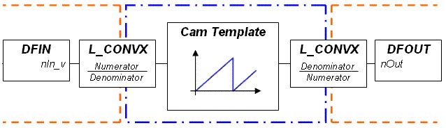
If due to the machine variables 'mater value-gearbox ratio' and 'feed constant of a real master drive' a non-integer x-clock pulse length arises, the clock pulse length can be represented on an incremental integer value by using a transformed master axis and before the master value information can be scaled by means of a suitable converter module (e. g.
L_CONVX function block).
Evaluation:
The behaviour occurs because a corresponding remainder (decimal places of the x-clock pulse length) is not available in the function blocks mentioned above and can therefore not be considered when the phase difference signal is formed. As a result, a drift in x-direction occurs.
Example:
A load-side clock pulse length of 250 mm driven via a gearbox ratio z2 : z1 = 1978 : 189 and a feed constant of 400 mm/rev is converted in an incremental value of 428671.322751323... [inc.]. The decimal places (in the example 0.322751323 [inc.]) are not considered in the incremental value. Thus 0.322751323 [inc.] too little are considered with every machine clock pulse and in comparison with the original clock pulse, the clock pulse generated from the phase difference signal falls back.
Application of a transformed master measuring system: see article
200411594