Which products are affected?
9300 vector 0.37…90 kW SW V7.1
Applications
Connecting the drive controller to a coasting machine, e. g. a fan.
Function description
After determining the current machine speed by means of the flying restart circuit the drive controller will be synchronised to the connected machine. During the synchronisation phase the output frequency is increased along a ramp to the frequency-dependent output voltage. Meanwhile the ramp function generator in function block NSET is stopped. This process may take several 10 ms. If a current overshoot is observed during the synchronisation phase it may be useful to further increase the period of time in which the ramp function generator is stopped with code C0133. According to the Lenze setting code C0133 is set to 100 ms. The parameter can be set in 1 ms steps from 0 ms to 9999 ms.
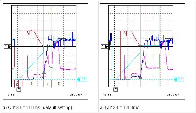
The figures attached show the influence of C0133:
In oscillogram a) a minimum decay time of C0133 = 100 ms between start of the voltage ramp and release of the ramp function generator is selected. In this case the actual decay time is approx. 380 ms due to the rise in the voltage ramp and the end of the synchronisation phase.
Oscillogram b) shows that the decay time is prolonged exactly to the minimum decay time set under C0133 = 1000 ms.
In both cases the synchronisation phase does not show excessive current oscillations. Therefore, the Lenze setting (100 ms) selected under C0133 does not have to be changed. The current rise during the slope of the ramp function generator is the appropriate acceleration current.
Description of the phases of a flying restart circuit (see designation of the phases in oscillogram a):
1. Controller is inhibited via terminal 28.
2. Controller is enabled via terminal 28 but the minimum time of the controller inhibit specified under C0132 (here 496 ms) has not yet expired.
3. Start of flying restart circuit and injection of search current. Since the machine has not yet been de-excited sufficiently a peak current occurs at first and the search current injection is restarted. The search frequency is indicated under MCTRL-FACT.
4. By determination of a current minimum the controller recognises that the search frequency corresponds to the current machine speed. The output voltage MCTRL-VACT is increased along a ramp in the following synchronisation phase.
5. When the synchronisation phase has been completed and the decay time under C0133 has expired the ramp function generator is re-enabled and the motor is accelerated to the setpoint speed. The flying restart circuit has been completed successfully.
Fig.: Signal characteristic when executing a flying restart circuit as a function of C0133
CH1 (pink): Motor current MCTRL-IACT (10 % / div)
CH2 (red): Rotating field frequency MCTRL-FACT (2 % / div)
CH3 (blue): Output voltage MCTRL-VACT (20 % / div)
CH4 (turquoise): Setpoint speed MCTRL-NSET2 (20 % / div)