Question:
What adjustment strategy is recommended in order to determine the ideal position and speed controller settings?
Answer:
i950, i700 servo inverter and other controllers:
In order to optimise the controller settings for the position and speed control loop, we recommend the adjustment strategy according to Ziegler & Nichols in practise.
With the optimum controller settings thus determined you will achieve an optimum dynamic drive performance with regard to stability, following error characteristic, position accuracy, and behaviour when reaching the target.
"Less is more" stands for the following conviction:
- For an optimum, dynamic drive behaviour it is often not useful just to select the maximum permissible speed controller gain (Vpn) close to the stability limit.
- It would be far better to deliberately select a much lower Vpn setting (less is more) whilst at the same time selecting a higher position controller gain Vpp.
- As a result, there will be a minimum for the optimisation quality criterion "square-law following error" and
- an appropriate distance to the stability limit will be observerd (stability reserve) in order to ensure safe (stable) operation in all operating states of the machine even if the plant or ambient parameters slightly change during operation.
Square-law following error as a function of the Vp settings of speed and position controller (example measurement):
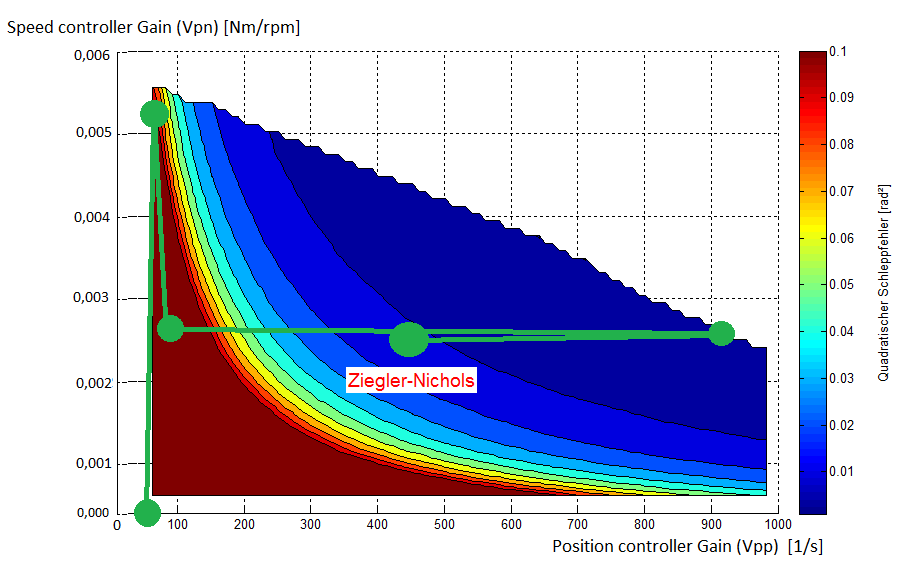
How to read the above diagram:
The following error behaviour is displayed in different colours. The colour scale on the right indicates the quality (dark blue = best quality).
In the area above the limit, from blue to white, the drive shows an unstable behaviour and a semi-stable vibration occurs in the drive system.
The green lines and dots outline the steps for controller adjustment according to Ziegler & Nichols:
- Raise the speed controller Vpn up to the stability limit and subsequently reduce it to 45% of the maximum value.
- Raise the position controller Vpp up to the stability limit and subsequently reduce it by 50%.
The Vpn/Vpp combination according to Ziegler&Nichols will determine a praxis-oriented optimum (Quality criterion , distance to stability limit).
Idea: If you set Vpn to a maximum value just below the stability limit, the position controller gain Vpp could only be slightly raised (x direction). Such a Vpn/Vpp combination would usually be in the red/yellow area and you would be close to the stability limit - i.e. no optimum setting for the quality criterion used.
AutoTuning Funktion:
AutoTuning is an automatic procedure for optimising the controller settings for the position and speed control loop, based on the adjustment strategy according to Ziegler & Nichols.
With the following Lenze device series the function AutoTuning is available:
- Servo inverter i950 from firmware V01.06.04
- Servo inverter i700 from firmware V02.16.00
Background information:
Position and speed control loop:
The optimum controller settings for these two control loops are mainly influenced by the characteristics of the controlled system, i.e. the machine itself.
The properties of the controlled system are usually not exactly known beforehand: moment of inertia of the load mechanics, ratio between the moments of inertia of the load and the motor (kJ), gearbox backlash, elasticities, torsional influences, friction forces within the mechanical components. The properties of the controlled system may change during operation.
Therefore, the controller settings can only to a limited extent be optimally preset.
Usually, the controller settings have to be adjusted when commissioning the complete machine.
Current controller settings:
Unlike the higher-level control loops, for the adjustment of the subordinate current control loop, only the electrical data of the motor and the controller are decisive. The mechanical parameters of the machine to be driven have no impact on the current controller settings.
Therefore, for Lenze motors, the optimum current controller settings can already be peset from the catalogue. Normally, there won't be any further adaptations required later on.
Quality criterion "Square-law following error":
A quality criterion for evaluating the drive behaviour is a minimum square-law following error during positioning. Usually special focus is on the behaviour along the ramps and especially on the behaviour when reaching the target. By squaring the occurring following error characteristic, the as a matter of principle higher position deviations in the acceleration and deceleration phases compared to the behaviour while travelling at constant speed are weighted higher.
