
MELSEC Communication Protocol
Supported hardware and firmware
Cloud Notify via MELSEC Communication Protocol is supported on the x500 in firmware 3.17 and up, for the following Mitsubishi PLCs:
- MELSEC-L Series: LO2CPU-P*
- MELSEC-Q Series
- MELSEC iQ-R Series: R08CPU*
- MELSEC iQ-F Series
other CPUs in this series may also be supported, but are unconfirmed.
Please upgrade your firmware if you are running an older version.
Activate Cloud Notify
Please first activate Cloud Notify (or start the 30 day free trial) if you haven't already.
The Second step in Cloud Notify is setting up a data source. This is done by selecting a communication protocol and defining the variables. This article shows you how to do this for a Mitsubishi PLC in both MELSOFT GX Works2 and GX Works3.
PLC settings
Depending on the type of Mitsubishi PLC you’re using, the setup of the PLC has to be performed in either GX Works2 or GX Works3:
- L and Q series are set up using GX Works2.
- iQ-F and iQ-R series are set up using GX Works3.
GX Works2
Setting up the CPU Module enables the PLC to communicate with an external device (i.e. the x500). This can be done by following the next steps:
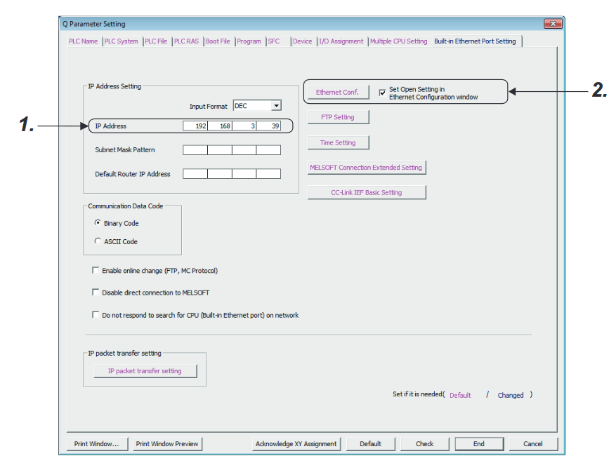
- In the Project Window, open [Parameter] > [PLC Parameter] and go to the tab [Built-in Ethernet Port Setting].
- If you haven’t already, enter an IP address for the CPU Module (indicated by #1) and a Subnet Mask Pattern (usually 255.255.255.0).
- Check the option “Set Open Setting in Ethernet Configuration window” and press [Ethernet Conf.] (indicated by #2).
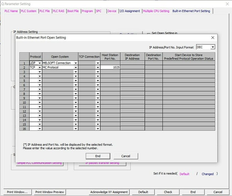
- On a new row, select protocol “TCP”, select open system “MC Protocol” and choose a Host Station Port Number between 1025-4999 or 5010-65534.
TCP or UDP?
We support both the TCP and UDP protocol, but recommend using TCP as this protocol is less error-prone.
Next step
Your PLC is now ready and you can continue setting up the x500 by selecting a communication protocol.
GX Works3
Setting up the CPU Module enables the PLC to communicate with an external device (i.e. the x500). This can be done by following the next steps:
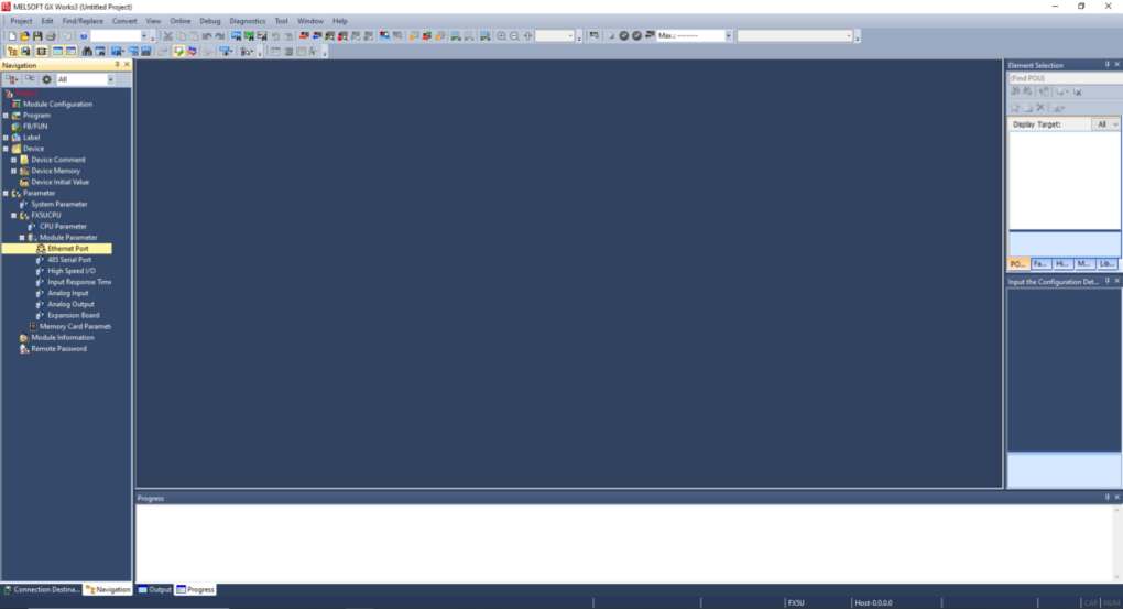
- In the Navigation pane, go to [Parameter] > [CPU] (FX5UCPU in the example below) > [Module parameter].
- Open the [Ethernet Port] parameters.
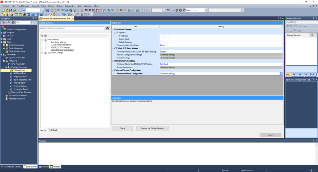
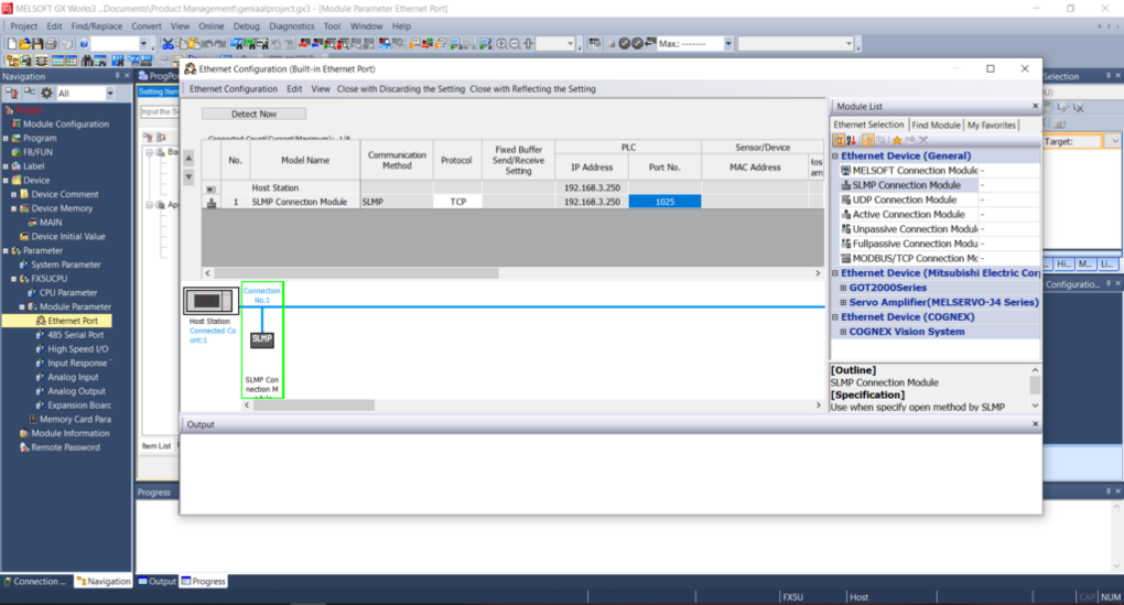
- Expand [Basic Settings] in the Item List and double click [External Device Configuration].
- Expand Setting Item [External Device Configuration] and open the External Device Configuration window by double clicking “<Detailed Setting>“.
- Expand [Ethernet Device (General)] in the Module List.
- Drag and drop [SLMP Connection] into the grey area. This is the MELSEC Communication Protocol.
- Select protocol “TCP” and choose a Port No. between 1025-4999 or 5010-65534.
- Save the setting by pressing [Close with Reflecting the Setting] at the top.
- [Apply] the new project setting.

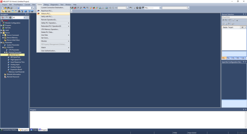
Now all that’s left is to write these settings to the PLC.
- In the top menu, press [Online] > [Write to PLC…].
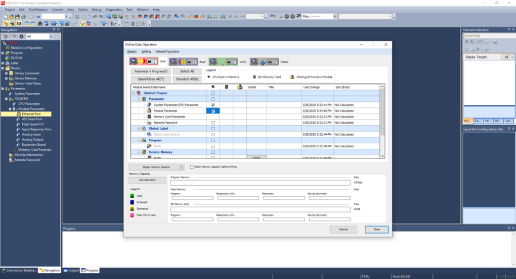
- Expand [Parameter], make sure “Module Parameter” is checked, and press [Execute].
TCP or UDP?
We support both the TCP and UDP protocol, but recommend using TCP as this protocol is less error-prone.
Next step
Your PLC is now ready and you can continue setting up the x500 by selecting a communication protocol.
Select a communication protocol
You first have to select a communication protocol. This is the protocol that the x500 will use to communicate with the PLC.
- Go to the Fleet Manager app, which is accessible from the Apps menu in the top right corner if you are currently in a different X4 Remote app.
- Open the Main menu, go to Devices, and select the concerning device.
- Click on the Add a service icon in the left menu, select [Data source], and then select [MELSEC Communication Protocol].
- Enter the requested information (details below) and click on [Add].
| Variable | Description |
|---|---|
| Name | Enter a name for the data source. |
| Identifier | The identifier ensures that every data source remains unique, even if they share the same name. |
| IP address | Enter the IP address of your PLC. |
| Port | Enter the Port No. that you configured in your PLC. This is named “Host Station Port Number” in GX Works2. |
| MELSEC Serie | The Mitsubishi MELSEC PLC series to which your PLC belongs. If you’re unsure, please consult the Mitsubishi website. “QnUCPU” is Mitsubishi’s notation for every MELSEC-Q Series PLC with CPU type Q..U..CPU, for example Q04UDVCPU or Q26UDEHCPU. |
| Transport protocol | Select the same protocol that you configured in your PLC. |
| Network No. and PC No. | If configured in the PLC, enter the correct settings here. If not, leave the default settings. Applicable when using a custom MELSEC PLC network. |
| Request destination module I/O No. and Request destination module station No. | If configured in the PLC, enter the correct settings here. If not, leave the default settings. Applicable when using a specific I/O module for communication. |
| Authentication type | The Ethernet connection in the PLC may be password protected. Enter the password or leave it empty if no password is configured on the PLC. |
| Polling sleep time | To log data as accurately as possible, the x500 continuously asks the variables’ values from the PLC (this does not count towards your license’s dps/hr). While the x500 does wait for the PLC to reply before asking again, in very rare cases this may noticeably impact the PLC’s performance. In such a rare situation you may want to change this setting to 100ms or higher. In general “None” is recommended for Cloud Logging to be as accurately as possible. |
Add variables
Once you’ve added a data source and selected a communication protocol, you can start adding variables.
You can do this by following the steps below:
- Expand the Data source service and go to [Variables].
- You can now choose to:
- Manually add new variables
- Import variables from a file (or device)
Tip!
It is advisable to add variables in small batches and test them to verify their configuration.
Manually add new variables
- Click on [Add variable] in the bottom right corner.
- Enter the requested information (details below) and click on [Add].
Use GX Works to find these values for each variable that you want to use.
| Field | Description | ||||||||||||||||||||||||||||||||||||||||||||||||||||||||
|---|---|---|---|---|---|---|---|---|---|---|---|---|---|---|---|---|---|---|---|---|---|---|---|---|---|---|---|---|---|---|---|---|---|---|---|---|---|---|---|---|---|---|---|---|---|---|---|---|---|---|---|---|---|---|---|---|---|
| Name | Enter a name for the variable. | ||||||||||||||||||||||||||||||||||||||||||||||||||||||||
| Identifier | The identifier ensures that every variable remains unique, even if they share the same name. | ||||||||||||||||||||||||||||||||||||||||||||||||||||||||
| Type | Select the variable’s data type (bool, int, float, etc). | ||||||||||||||||||||||||||||||||||||||||||||||||||||||||
| Device type | Select the variable’s device type (register type). Each type requires to be entered in either decimal or hexadecimal notation, details below.
| ||||||||||||||||||||||||||||||||||||||||||||||||||||||||
| Device No. | Enter the variable’s address. | ||||||||||||||||||||||||||||||||||||||||||||||||||||||||
| Factor | Multiplies the value (leave empty if the data type is boolean). | ||||||||||||||||||||||||||||||||||||||||||||||||||||||||
| Unit | Displayed text behind the value. |
Temporary disconnect
After this next step, the config push, the device may temporarily disconnect and LAN communication may be temporarily interrupted while it's applying the new settings. This may take a minute.
You have now made the changes in X4 Remote, but these are not yet active in your device. You will need to push your changes to your device for them to take effect.
- Click [Push config to device] in the top right corner.
Next step
Now that you've added the variables, you can test if they're configured properly.
Import variables from a file (or device)
You can easily and effortlessly copy variables from one device to another by exporting the concerning variables (view the “Manage variables” part of this article) and then importing them in your new device. Alternatively, you can manually prepare your variables in the required CSV format to load them all at once into your configurator. The CSV file structure is explained in our Import variables article.
- Click on [Import from CSV-file] in the top right corner of the screen.
- Select a CSV file to import and click on [Open].
Temporary disconnect
After this next step, the config push, the device may temporarily disconnect and LAN communication may be temporarily interrupted while it's applying the new settings. This may take a minute.
You have now made the changes in X4 Remote, but these are not yet active in your device. You will need to push your changes to your device for them to take effect.
- Click [Push config to device] in the top right corner.
Next step
Now that you've added the variables, you can test if they're configured properly.
Test variables
The test utility is used to check if all the added variables are set correctly. It shows the communication status with the PLC and displays each variable’s current value if everything is configured correctly. If not, the values will stay empty. The test utility will attempt to update values every 0.5 seconds, regardless of how often it’s actually being logged (this does not count towards your license’s dps/hr). Please follow the steps below to test your variables.
- Expand the Data source service, go to [Variables], and click on [Run test] at the top.
A connection will now be set up to stream the data directly to your computer, using:
| Port | Transport protocol | Application protocol |
|---|---|---|
| 443 | TCP | WebSocket |
You will see live values of all variables, if the configuration is set up correctly.
Unexpected result?
If the test utility shows unexpected values, please check if the addresses and data types of all variables are entered correctly. If you get an error message, please check Common error messages for more info. If you get no data at all, please also check that the above listed port and protocols are not being blocked by your computer's or company's firewall.
Next step
Now that you've tested the variables, you can view our "Configure data tags" guide to start logging.
Manage variables
You can view all defined variables on the variables page:
- Expand the Data source service and go to [Variables].
You can [Edit] individual variables, [Remove] individual or a selection of variables, and export all or a selection of variables.
Variables can be selected by clicking the checkbox on the left, or you can select them all by clicking the checkbox at the top.